Remaking the cube.
This one is controversial! It is the most used object in blender. The problem is we need to stop thinking about a cube as having six sides.
First things first - The cube in the video is not the best cube to use in blender! The reason I used this version in the video is to help you get used to the idea that objects have a top, a cross section and a bottom.
There is a better topology which uses 6-spoked poles on the corners and it is this which is the perfect topology for the cube. There is another cube wshich has 14 sides and has many uses in modelling too!
A Cube; a regular hexahedron, a square parallelepiped, an equilateral cuboid and a right rhombohedron. One of the five platonic solids. Don’t worry! All Useless facts to us as modellers because we dont care about the math behind its composition. We only care how it looks when it has a subdivision surface modifier applied to it.
As a simple polygon model, it looks great. As a subdivision surface it looks nothing like a cube - more of a ball - and it needs a lot of work. There are several common solutions to making it look good. The video above goes through them but here I will show you the method which gives the most realistic reaction to light.

The Blender Cube

The Blender Cube with Subdivision
Often the cube is simply subdivided many times until the required sharpness of the edges and corners is achieved. This results in very heavy meshes with potentialy thousands of vertices and is not a method I would ever recommend.
The most common, and arguably the most sensible method, is to apply a bevel modifier to the cube. Any even amount of bevels will avoid triangles and the resulting geometry is lightweight and easily adjustable. It can be difficult to connect this cube to other meshes and more geometry may need to be added. You wont have good, individual control over the curvature over various edges but this is a good and common basic method.
The one we will use is the least common method but provides the best renders, the most control and is completely in keeping with the idea that objects in subdivision surface modelling have a top, a bottom, a cross section and boundaries which handle the areas of transition between these elements.
That is not to say that it does not have it’s problems. You will not use it often, but handling future objects with cubic parts will be made easier by understanding the basic principles involved.
01 | N-Poles.
Lets talk a bit more about vertices with only 3 edges connected to them. 3 spoked poles or “N-Poles”. If you want to do things properly for really close up work, then you need to know what they are and why they cause problems.
If we are modelling in quads they are essential. They will appear in your models a lot. They cant be avoided the way that n-gons and triangles can; but they can cause problems if you dont know what to do with them.
They represent a boundary and a new direction of flow through the model so putting them on corners seems like a logical place for them; but they do cause an unavoidable pinching of light when rendered and to avoid this, corners should really be 4-spoked poles (natural poles), not 3.
Since they are inevitable, the best thing you can do with them is hide them on the flattest, “least likely to suffer distortion” part of a model you can. Ideally they should be within 2 loops from a boundary edge as this is the usually the place least likely to suffer from distortion problems.
If they are at the very point of a corner they are often considered to be acceptable. Most of the time, the light pinching effect is so small that no one cares, but you can get a better result by making sure your corners have 4 spokes coming out of their vertices and your overall modelling technique will be much stronger if you consider them to be bad on corners that are going to be seen up close.
This is something we call "termination" but I will cover this concept more in a later tutorial.
02 | Ideas about topology : The dice.
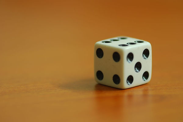
Six sided dice are objects that you think of as being a type of cube in the real world.
When you see a dice on a table, you would perhaps say that you rolled a “6” because that is what is on the top. If i asked you: “where is the 4?”, you would say it is on the side. If I asked you "where is the 5?" You would also say it is on the side.
.jpg)
Beyond Compass directions, We don’t really have good methods for describing the orientation of the sides in spoken language because notionally we think of the other numbers as being just on “The Side”.
In 3D we think of this collection of sides as the cross section. Knowing the nature of the arrangement of numbers on a dice you would also say that the “1” is on the bottom.
It is this intuition we must leverage when considering the topology of a cube (and ultimately everything except for a sphere) in 3D subdivision surface modelling.
The only thing you need to accept at this time is that a cube does not have six sides! It has a top a bottom and a cross section. It is similar to the cylinder but with added loops to shape the corners.
It’s all sounding a bit abstract so I think the best thing to do is get on with making one. You will see how simple it is really.