Remaking the Cylinder.

Blender provides us with a cylinder with two options for the endcaps which both cause problems with the subdivision surface modifier.
In polygonal modelling, shapes change at will and in anyway you want. In subdivision surface modelling we need to think about areas of transition when things change shape.
This is the first object we will tackle that requires some thinking about how objects are really composed.
The best way to think a cylinder is that is has a top, a bottom, a cross section and some areas of transition between these things.
These transition areas are lacking in blenders cylinder - and in fact in all polygonal models. This may seem obvious but what we will do here is essential thinking in creating anything suitable for subdivision surface modelling.
The Blender Cylinder
These areas of transition are the main difference between polygonal modelling and subdivision surface modelling.
We don’t want to model curvature, we want to control it. This is where these boundaries become necessary.
These ideas will become important when we talk about the cube and essential when we make the Rook for our chess set.
We will also start to concern ourselves with 3-spoked vertices or 'N-Poles' in our models and how best to position them.
The blender primitive cylinder comes with either an 'n-gon' cap or you can choose to have a mass of 'triangles'. Neither will work with the subdivision surface modifier as shown below.
Subdivided N-gon cylinder


Subdivided triangle cylinder
This is the easiest of the primitives to fix but we can make some good discoveries here about how subdivision surface models work so the descriptions of what we are doing will be a little longer. It is really worth trying to understand exactly what is happening at each stage.
01 | Add a blender cylinder.
Press “Shift-A” and select 'Mesh' then 'Cylinder' from the pop up menu.

Cylinder creation options
This gives us one of blenders primitive cylinders with an N-gon cap. An N-gon in blender is generally assumed to mean a polygon with more than 4 edges and they cause problems with subdivision surface modifiers so we want to avoid when possible.
In the properties dialogue box in the bottom left hand corner of the 3D viewport window, we can change the vertices to “8”.
8 is a good number in subdivision surface modelling and we will see it cropping up a lot.
8 vertices will allow the cylinder to be perfectly circular across its cross section without adding unnecessary geometry.
Before we do anything it is worth noting that all of the vertices around the top and bottom of our cylinder have only three edges connecting them. These are called N-poles and always indicate a change in the direction of flow around a model. They are unavoidable but they should always appear on the flattest area of a model you can find in order to hide their influence from the subdivision surface modifier. This is not as difficult as it may sound and they are mostly moved with very natural modelling processes.
The Vertices at the top of the cylinder are N-poles (3-spoked poles).

02 | Create loops to control curvature.
While we do eventually want to get rid of the n-gons, they are useful at this stage so we can press “Tab” to go to edit mode, and hit “3” on the numberline to use face select mode.
Now select the top face and shift select the bottom face of our cylinder. We will use these two faces to create our first area of transition.
Press “i” to inset these faces and immediately type “0.1” to create a new closed loop 10% of the distance inside them.
This will be a 'control loop' which we use to change the profile of the curve over the edge of the cylinder.

Insetting the top face

We have now created our first area of transition and, at the same time, moved our 'N-Poles' onto a flat surface.
The top edge of our cylinder is now made entirely of vertices with 4 connecting edges - natural poles. Perfect.
Press “i” again but this time type “0.5”. This new loop is a 'holding loop' and will not be moved.
Our 'N-Poles' have now been moved even further away from danger and are in an optimal position - 2 loops away from the 'structural loop' over the lip of the model.
The second inset
I often like to borrow some functionality from the UV-system (normally used to help create UV maps) to help identify which loops are actively controlling our curvature. This turns the edges which make up a loop red making it easy for us to identify which loops control the curvature within a boundary. This step is not necessary but it does help to keep track of your loops when modelling.
Seams must be marked on edges within edit mode so press "2" on the number line of your keyboard to make sure you are in edge selection mode.
“Alt-click” the first loop after the edge of our cylinder on the flat surface of the top of our model to select it.
“Right-click” anywhere in the 3d-viewport and select 'Mark Seam' in the pop up menu. This loop will now be displayed in red on the model which helps us to keep track of which loops are important in changing the curvature between our areas.

A control loop marked in red using 'Mark Seam'
The 'n-gon' faces in the very center of the top and bottom of the cylinder have served their purpose now and should be deleted. Press "3" to change to face select mode and selectithem both (in the middle of the top and bottom of the cylinder.) Hit “del” or "x" and choose 'faces' from the pop up menu to get rid of them.
N-gons do not work well with the subdivision surface modifier and as modellers we need to understand that we will have no control over the final usage of our models. We need to give them the ability to distort in as many possible ways as possible while remaining quad based. Someone further along the production may decide that the model will be crushed, twisted, made from cloth, sucked into a black hole, melted, be made transparent, brought to life with an armature or one of another thousand creative possibilities. Your model should be ready for as much abuse as a creative team can throw at it; or at least be easily adaptable for these options.
Something that begins life as a scene prop can quickly become a necessary object for a character to interact with and your models should be ready for any possibility. A prop in a scene should be reusable across many production, episodes of a series or versions of a game. If a production is remastered or rebooted, the models used in it will need to be updated and if they do not have good quad topology, they will need to be remade and that will reflect very badly on you as the modeller.
Models in games are triangulated for their use within that game but the original quad based model with good control is the basis for these triangulated game versions and the ability to adapt these to the designers needs or update them for a new version or remaster of that game relies on the model having flexible topology to make the changes. This model is often referred to as The Framework Mesh. Models with n-gons are considered unusable in a production pipeline and any models containing them will be rejected at some point in the production.
Now, hover over any of the edges which surround the hole at the top of the model and “Alt-click” to select all of the edges which make up this loop.

Blender provides a very useful command called 'Grid Fill' which can be found in the 'Face' menu.
Select 'Grid Fill' now to fill in the hole at the top with quads.
Repeat this process for the n-gon faces on the bottom of the model.
Grid fill to fill the hole with quads
I would normally use the 'offset' option in the 'grid fill properties box' in the bottom left hand corner of the 3d-view to align the grid fill with the axis of the scene. Increasing the offset value until they are aligned. This is not strictly necessary but it will help your model if distortion across one of the main axis ever occurs which is common when using the simple deform modifier or lattices. Try to remember that distortion is not simply a process which can happen during animation; it is also a modelling process. To avoid the often boxy looking models produced in hard surface modelling, many other processes will be used to create our framework meshes.
Two more control loops can be added to increase our control of the curvature over the top of the model.
Change to face select mode (hit “3” on the numberline) and “Alt-Click” any of the vertical edges around the cross section of the cylinder.
This selects the 'ring' of faces around the entire model and pressing “i” to inset, then typing “0.1” as before creates two loops around the profile, 10% of the distance from the rims of the cylinder. Hit “Enter” to confirm this change.

Insetting to create control loops
Again, these new loops can be “Alt-clicked” in edge select mode (Hit “2” on the numberline) and marked as seams in either the “Right-Click” menu or the 'UV menu' to visually identify them as 'control loops'.
At this point you may notice that two 'control loops' are separated only by faces; not extra loops, so i would often add a 'holding loop' between them. To do this simply hover over the center of the cross section and press "Ctrl-R" to add a loop. "Left-Click" to confirm that you only want one loop then "Right-Click" to tell blender that we want to leave it exactly in the middle of our two 'control loops'.
03 | Controlling the curvature.
We generally don’t move 'control loops' along an axis. We slide them along a safe area that we create on a mesh called a boundary.
When you want to move a control loop we would normally select it by “Alt-Clicking” on one of the edges that make up the loop then we press “gg” (twice in quick succession) to go into edge slide mode.
Now the loops can move exactly in the direction they need to go within areas of safety we have defined in order to control our curvature. We don't often need to worry about which axis to use when moving loops.
Now, “Tab” back into object mode, add a subdivision surface modifier (with “Crtl-3”) and select smooth shading by “Right-Clicking” in the 3d viewport and selecting 'Smooth' from the pop up menu.
By pressing the 'on-cage' button in the subdivision surface modifier we can see the proper curvature and the controls we highlighted while working in edit mode.
It can be confusing to work with on-cage turned on so get used to turning it on and off a lot!

The 'On-Cage' Button

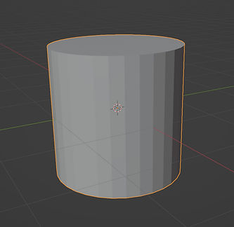
The final cylinder
We now have a cylinder made from all quads with excellent control over the curvature between our top, bottom and cross section.
It is made from 74 vertices.
We dont have to worry about moving 'control loops' along a particular axis as we can always press “gg” to move them safely and correctly to change the curvature over the edges of the cylinders lip.
It will be correctly and efficiently triangulated at any subdivision level.